Interface Design
JOSIF Main Page | JOSIF Guidebook | Modeling | Interface Design
Interface Design
When designing interface services from the ground up, it is helpful to categorize them according to a set of preexisting service models. These models establish a proposed context and boundary within which the service can be modeled. Common service models include application services, entity-centric business services, and task-centric business services. These establish the utility-centric, entity-centric, and task-centric service contexts, respectively.
Furthermore, interface services are the enabling blocks to deliver contracts. So their definition should be aligned with the work on Contracts done in GB942.
An Entity-centric interface is mainly focusing around some entities, like Problem, TT or Alarm and is mainly aiming at managing the lifecycle of these entities. It establishes business services that represent a specific business entity, the entity being managed. The labeling of entity-centric business services is often predetermined by the entity name, combined with a verb, like CreateTT.
An entity-centric interface contains both an Information Model part and an Operational Model part.
A Task-centric interface is encapsulating process logic or use case steps. In this case, the thread that ties together the grouped logic or steps is a specific activity being automated by the service logic. Consequently, the use of verbs in service names is common.
A task-centric interface acts on some data model, but not directly managed by this interface. An Inventory interface for instance will act on the whole Resource model, but won’t manage the lifecycle of each resource object.
A task-centric interface might contain some “owned” Information Model. For instance, an Order Management interface will “own” a Service Order entity, but through this object, will act on the whole Service model.
The definition of services provided above is aligned with GB942, for which the Contract becomes a fully standardized interface specification. The TIP interface services are the underlying building blocks onto which Contracts are layered. The same TIP interface service might be reused in multiple Contracts.
Service Interfaces
An interface can be seen or decomposed into 2 layers
- The communication vehicle. Examples of communication profiles such as JMS, http/SOAP, etc
- The exposed service. It can be a method in a code definition, or a set of formatted input/output/fault messages for example.
This guidebook focuses on definition and pattern applying to the second layer and will rely and use the existing pattern and usual usage of the “communication vehicle”.
The way and the naming convention that allow an application to declare/expose or to find/consume services from an interface depend a lot form the technologies themselves. A string representing an URL is used for the Web Services. These mechanisms and naming conventions are detailed in the technology specific Guidelines. It is important to note that the version of the interface is always present when finding or accessing the OSS service.
Before going into the details of the patterns and definitions related to services, it is important to define the meta-model that will governe TIP.
An interface package must define at least one interface service and might additional ones as needed.
Each interface can have zero or more associated Entities.
Each interface can have zero or more associated Notifications that it will expose.
The diagam below shows a simplified meta-model of a TIP interface package.
Interface Project vs Dependencies
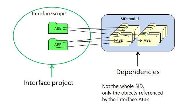
The scope of an interface project is a set of ABEs (Aggregated Business Entities). For each ABE, the whole package has to be part of the interface project.
The numbers of ABEs associated with an Interface can be zero for pure task-centric interfaces, like an Inventory interace, 1 or more for entity-centric interfaces.
However, the interface, even if it does not manage the lifecycles of objects in some ABEs, will act or reference a number of objects. Those objects are called Dependencies. For implementation purpose, they will be isolated in a Dependencies project.
The picture below illustrates this concept:
Dependencies can be:
- A parent class for a class present in the interface project. Eg. BI for Trouble Ticket
- Relationships/ associations. If an object in the interface scope references other objects, then these objects would be part of the needed references.
- Composition. A class (entity or datatype) used by composition, for instance for an attribute.
- Parameters that will be used by the operational model. A class or datatype used as a parameter of an operation of this interface.
